Redis Enterprise for Kubernetes architecture
This section provides an overview of the architecture and considerations for Redis Enterprise for Kubernetes.
Redis bases its Kubernetes architecture on several vital concepts.
Layered architecture
Kubernetes is an excellent orchestration tool, but it was not designed to deal with all the nuances associated with operating Redis Enterprise. Therefore, it can fail to react accurately to internal Redis Enterprise edge cases or failure conditions. Also, Kubernetes orchestration runs outside the Redis Cluster deployment and may fail to trigger failover events, for example, in split network scenarios.
To overcome these issues, Redis created a layered architecture approach that splits responsibilities between operations Kubernetes does well, procedures Redis Enterprise Cluster excels at, and the processes both can orchestrate together. The figure below illustrated this layered orchestration architecture:

Operator based deployment
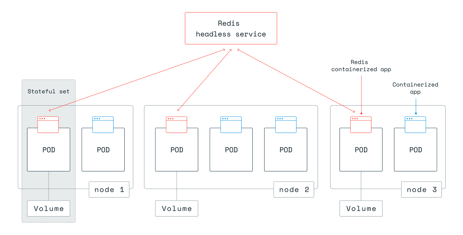
Operator allows Redis to maintain a unified deployment solution across various Kubernetes environments, i.e., RedHat OpenShift, VMware Tanzu (Tanzu Kubernetes Grid, and Tanzu Kubernetes Grid Integrated Edition, formerly known as PKS), Google Kubernetes Engine (GKE), Azure Kubernetes Service (AKS), and vanilla (upstream) Kubernetes. Statefulset and anti-affinity guarantee that each Redis Enterprise node resides on a Pod that is hosted on a different VM or physical server. See this setup shown in the figure below:
Network-attached persistent storage
Kubernetes and cloud-native environments require that storage volumes be network-attached to the compute instances, to guarantee data durability. Otherwise, if using local storage, data may be lost in a Pod failure event. See the figure below:
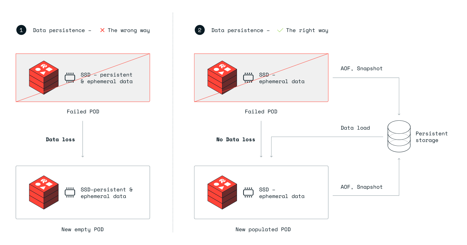
On the left-hand side (marked #1), Redis Enterprise uses local ephemeral storage for durability. When a Pod fails, Kubernetes launches another Pod as a replacement, but this Pod comes up with empty local ephemeral storage, and the data from the original Pod is now lost.
On the right-hand side of the figure (marked #2), Redis Enterprise uses network-attached storage for data durability. In this case, when a Pod fails, Kubernetes launches another Pod and automatically connects it to the storage device used by the failed Pod. Redis Enterprise then instructs the Redis Enterprise database instance/s running on the newly created node to load the data from the network-attached storage, which guarantees a durable setup.
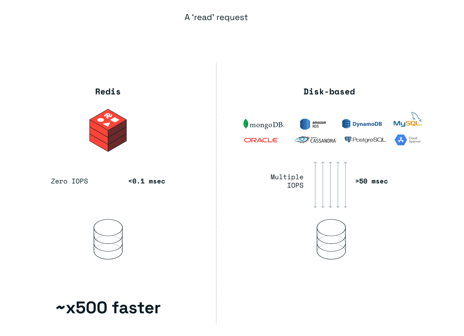
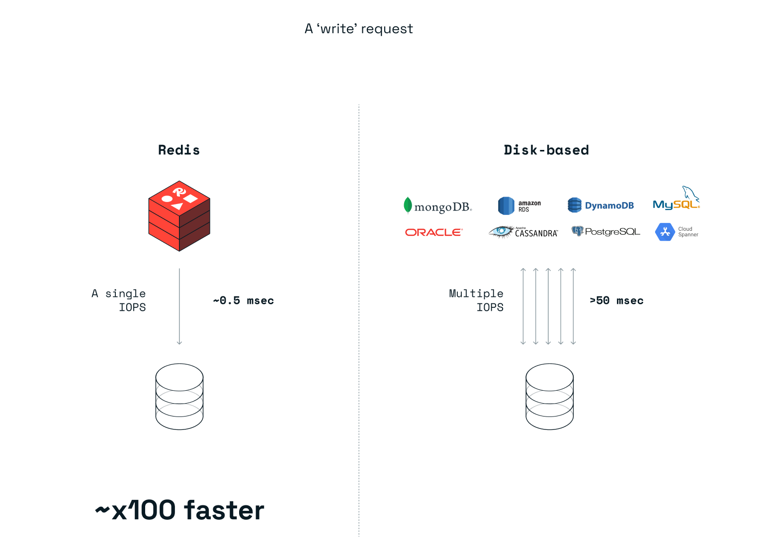
Redis Enterprise is not only great as an in-memory database but also extremely efficient in the way it uses persistent storage, even when the user chooses to configure Redis Enterprise to write every change to the disk. Compared to a disk-based database that requires multiple interactions (in most cases) with a storage device for every read or write operation, Redis Enterprise uses a single IOPS, in most cases, for a write operation and zero IOPS for a read operation. As a result, significant performance improvements are seen in typical Kubernetes environments, as illustrated in the figures below:
Multiple services on each pod
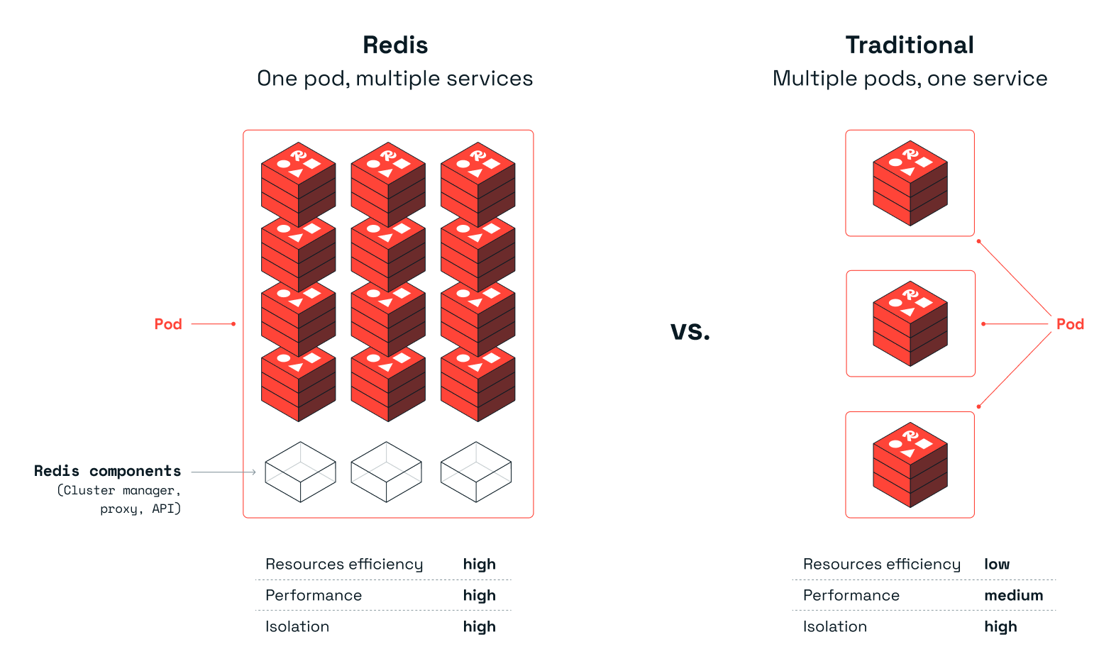
Each Pod includes multiple Redis Enterprise instances (multiple services). We found that the traditional method of deploying a Redis Enterprise database over Kubernetes, in which each Pod includes only a single Redis Enterprise instance while preserving a dedicated CPU, is notably inefficient. Redis Enterprise is exceptionally fast and in many cases can use just a fraction of the CPU resources to deliver the requested throughput. Furthermore, when running a Redis Enterprise Cluster with multiple Redis Enterprise instances across multiple Pods, the Kubernetes network, with its multiple vSwitches, can quickly become the deployment’s bottleneck. Therefore, Redis took a different approach to managing Redis Enterprise over the Kubernetes environment. Deploying multiple Redis Enterprise database instances on a single Pod allows us to better utilize the hardware resources used by the Pod such as CPU, memory, and network while keeping the same level of isolation. See the figure below:
